 LT
LT  RU
RU  EN
EN EtherCAT® Bus Coupler
 The EtherCAT® Bus Coupler connects the real-time Ethernet system with modular, extendable electronic terminal blocks. A complete unit consists of a bus coupler, a set of bus terminals and one end terminal.
{tab Features}
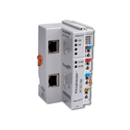
The ETHERCAT Coupler connects EtherCAT, the real-time Ethernet system, with the modular, extendable electronic terminal blocks. A unit consists of a Bus Coupler, a set of terminals, and one end terminal.
The Bus Coupler recognises the connected Bus Terminals and automatically allocates them into the EtherCAT process image. The Bus Coupler is connected to the network via the upper Ethernet interface. The lower RJ 45 socket may be used to connect further EtherCAT devices in the same strand.
In the EtherCAT network, the ETHERCAT Coupler can be installed anywhere in the Ethernet signal transfer section (100BASE-TX) – except directly at the switch.
EtherCAT (Ethernet Control Automation Technology) is the Ethernet solution for industrial automation, characterized by outstanding performance and particularly simple handling. EtherCAT enables the Ethernet star topology to be replaced with a simple line structure. Optionally, EtherCAT may also be wired in the “classic” way using switches, in order to integrate further Ethernet devices. The master requires no special plug-in card and can be implemented on any existing Ethernet controller using a very simple interface. EtherCAT is therefore also well suited to small and medium control applications, where it will also open up new areas of application for distributed I/Os.
For EtherCAT a separate I/O system in protection class IP 20 is available in the form of EtherCAT Terminals. In contrast to Bus Terminals, where the fieldbus signal is implemented within the Bus Coupler on the internal, fieldbus-independent terminal bus, the EtherCAT protocol remains fully intact down to the individual terminal.
The ETHERCAT Coupler supports the operation of all Bus Terminals. As far as the user is concerned, handling of the analog inputs/outputs is not different to other series. The information is available in the process image of the controller for processing in the form of a byte array.
The analog and multifunctional Bus Terminals can be adapted to each specific application. Depending on the type, the analog Bus Terminals’ registers contain temperature ranges, gain values and linearisation characteristics. The Bus Terminals store settings permanently and in a fail-safe manner. Optionally, the Bus Terminals can also be controlled by the control system. Via function blocks (FBs), the programmable logic controller (PLC) or the Programmable Automation Controller (PAC) handles configuration of the complete periphery during the start up phase. If required, the controller can upload the decentralized created configuration data in order to centrally manage and store this data. Therefore, new adjustments are not necessary in the event of replacement of a Bus Terminal. The controller automatically sets the required setting on power up.
{tab Specifications}
| System Data | AKT-ECT-000-000 |
| Number of I/O stations | 65,535 |
| Number of I/O points | depending on controller |
| Data transfer medium | Ethernet/EtherCAT CAT6 cable |
| Max. cable length | 100 m (100BASE-TX) |
| Data transfer rates | 100 Mbaud |
| Data transfer time | 0.01 ms in the case of 10 modules for 32 bit inputs and outputs each (without Standard Bus run-time) |
{tab Literature}
{tab Manuals}
{/tabs}